The Sagnac Effect
The Sagnac effect refers to the difference in optical path length caused by rotation. As depicted in Figure 1a, if an interferometer is fixed in an inertial frame, two beams of light - initially set off in opposite directions, are guided along a circular path of radius $R$ and detected by a detector at the initial position. Since the optical paths for the two beams are identical (equal to $2 \pi R$), there will be no phase difference at the detector if the beams were initially in phase.
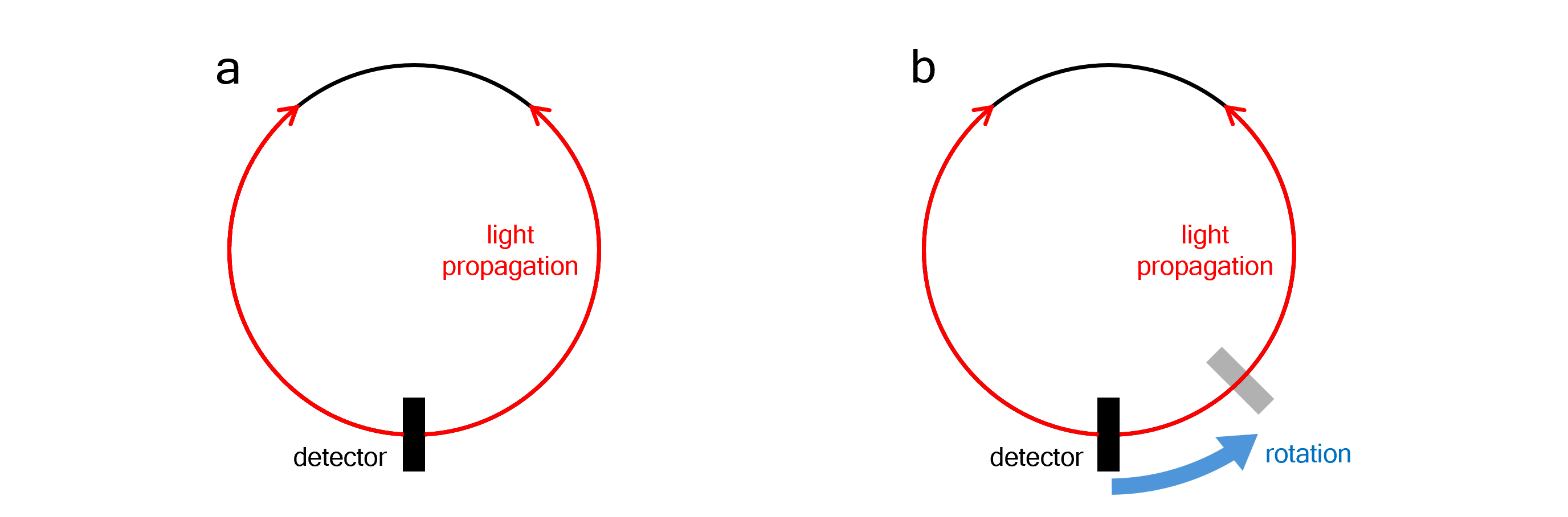 Figure 1 Sagnac interferometer setup. (a) without rotation, (b) with rotation relative to the inertial frame.
However, this is not the case when the interferometer setup is rotating relative to the inertial frame, as in Figure 1b. The rotation results in a phase difference at the detector.
An Observer in the Inertial Frame
The easiest approach to this problem is to view it from the inertial frame. While the light beams travel along the circumference, the detector itself rotates around the axis of the setup. Consequently, the optical path of the counter-rotating beam becomes shorter than $2 \pi R$, whilst the co-rotating beam travels an optical path longer than $2 \pi R$. Letting the angular velocity of rotation be $\Omega$, the equations for the travel time of the two beams, $t_{\rm counter}$ and $t_{\rm co}$, can be obtained as follows ($c=1$ is used for the rest of this article):
$$ (2\pi - \Omega t_{\rm counter})R = t_{\rm counter} $$ $$ (2\pi + \Omega t_{\rm co})R = t_{\rm co} $$
Solving for time:
$$ t_{\rm counter} = \frac{2\pi R}{1 + R\Omega}, \ t_{\rm co} = \frac{2\pi R}{1 - R\Omega} $$
Thus, the phase difference $\Delta \phi$ between the two beams is:
$$\Delta \phi = \frac{2\pi}{\lambda} (t_{\rm co}-t_{\rm counter}) = \frac{2\pi}{\lambda} \frac{4\pi R^2 \Omega}{1 - R^2 \Omega^2}$$
Where $\lambda$ is the wavelength of the light used in the interferometer.
An Observer in the Rotating Frame
Now, let us examine the rotating observer's perspective. Since the phase difference at the detector is related to the interference pattern, it must be invariant regardless of the observer's frame. The problem is, the frame is no longer inertial, and we are dealing with something that is really fast - light - which means from now on, relativity needs to be introduced.
The metric of this rotating frame can be derived from the relationship between the cylindrical coordinates of the two frames: $\phi = \phi^\prime + \Omega t$. More precisely, the transformation involves:
$$dt = dt^\prime , \ dr = dr^\prime , \ d\phi = d\phi^\prime + \Omega dt , \ dz = dz^\prime$$
Substituting these differentials into the flat spacetime Minkowski metric gives the line element in rotating coordinates:
$$ds^2 = -dt^2 + dr^2 + r^2d\phi^2 + dz^2 = -{dt^\prime}^2 + {dr^\prime}^2 + r^2(d\phi^\prime + \Omega dt^\prime)^2 + {dz^\prime}^2$$
Light moves along a null worldline ($ds^2=0$). Since the light is constrained to the path at radius $R$, the spatial trajectory enforces ${dr^\prime}^2 = {dz^\prime}^2 = 0$ and $r=R$. Therefore, we obtain:
$$dt^\prime = \pm R(d\phi^\prime + \Omega dt^\prime)$$ or $$dt^\prime = \pm \frac{R}{1 \mp R\Omega} d\phi^\prime$$
(i) The Counter-rotating Beam
Taking the lower sign corresponds to the counter-rotating beam, since $\phi^\prime$ decreases as $t^\prime$ increases. Integrating the both side:
$$ t_{\rm counter}^\prime = \int{dt^\prime} = \int_0^{-2\pi}{-\frac{R}{1+R\Omega} d\phi^\prime} = \frac{2\pi R}{1 + R\Omega}$$
(ii) The Co-rotating Beam
A similar expression is derived for the co-rotating beam by taking the upper sign:
$$ t_{\rm co}^\prime = \int{dt^\prime} = \int_0^{2\pi}{\frac{R}{1-R\Omega} d\phi^\prime} = \frac{2\pi R}{1 - R\Omega}$$
Finally, the phase difference $\Delta \phi^\prime$ between the two beams is calculated as:
$$\Delta \phi^\prime = \frac{2\pi}{\lambda} (t_{\rm co}^\prime-t_{\rm counter}^\prime) = \frac{2\pi}{\lambda} \frac{4\pi R^2 \Omega}{1 - R^2 \Omega^2}$$
This result is identical to the one obtained using the inertial frame approach, as expected.