In optics, etendue is a crucial physical quantity that describes the "spreading out" behavior of light. This article explains the definition of etendue and its most important property: conservation. Furthermore, we will explore how this conservation law limits the performance of modern AR/VR devices, and how engineers overcome these limitations.
Definition of Etendue

Figure 1 Definition of etendue. An infinitesimal bundle of light propagates through a surface element $dS$.
Suppose that a bundle of light, propagating in a medium of refractive index $n$, crosses through an infinitesimal surface element $dS$, at an angle of $\theta$ with the normal direction of $dS$. The infinitesimal solid angle over which the light bundle spreads out is $d\Omega$. The infinitesimal etendue, $dG$, of this light bundle is defined as:
$$dG := n^2 dS \cos\theta d\Omega$$
The term $dS \cos \theta$ is the area of the surface element projected onto the plane normal to the propagation direction. Therefore, the etendue can be interpreted as the product of the cross-sectional area occupied by the light bundle ($dS \cos \theta$) and its solid angle ($d\Omega$).
According to this definition, the total etendue of light crossing through a surface $S$ is calculated as:
$$G = \int_S \int_\Omega n^2 dS \cos \theta d\Omega$$
Here, $\int_\Omega$ denotes the integral with respect to the total solid angle occupied by light bundles passing through a specific point on $S$, and $\int_S$ denotes the integral over these points.
Note that the calculation of etendue is independent to the distribution of light intensity. Etendue is a purley geometric property: it soley depends on the geometrical coverage of light divergence.
Example 1: Etendue of a Light-Emitting Surface
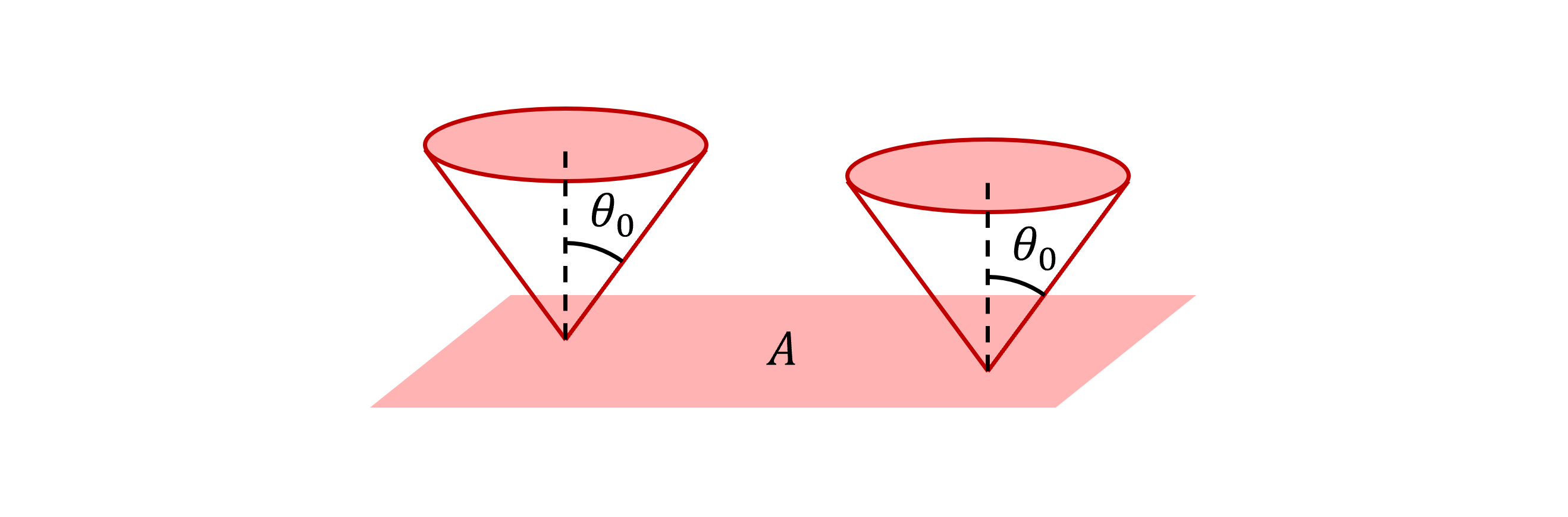
Figure 2 A flat light-emitting surface of area $A$. Each point is emitting light confined in a cone with a half-angle of $\theta_0$.
Now, let's dive into some hands-on calculations. Suppose a flat surface of area $A$ is emitting light as depicted in Figure 2 - you may think of is as an OLED panel. Assume that light emitted by each point on the surface is confined within a cone with a half-angle $\theta_0$, whose axis is normal to the surface. The total etendue of the light emitted from this surface calculated as:
$$G = \int_S \int_\Omega n^2 dS \cos \theta d\Omega = \int_S dS \int_\Omega \cos \theta d\Omega = \int_S dS \times \int_0^{2\pi}\int_0^{\theta_0}\cos\theta \sin\theta d\theta d\phi = A \times \pi \sin^2 \theta_0$$
Here, the refractive index $n$ is assumed as unity. It should emphasized that the total etendue is not exactly the product of the total area $A$ and the total solid angle $\Omega = \int_0^{2\pi} \int_0^{\theta_0} \sin \theta d\theta d\phi = 2\pi\left(1-\cos\theta_0\right)$, although the intuition holds true: etendue gets larger as the area and the solid angle of the light increase. The specific value of etendue relies on how each point on the surface emits and spreads light.
Example 2: Etendue of Light Propagating through Free Space
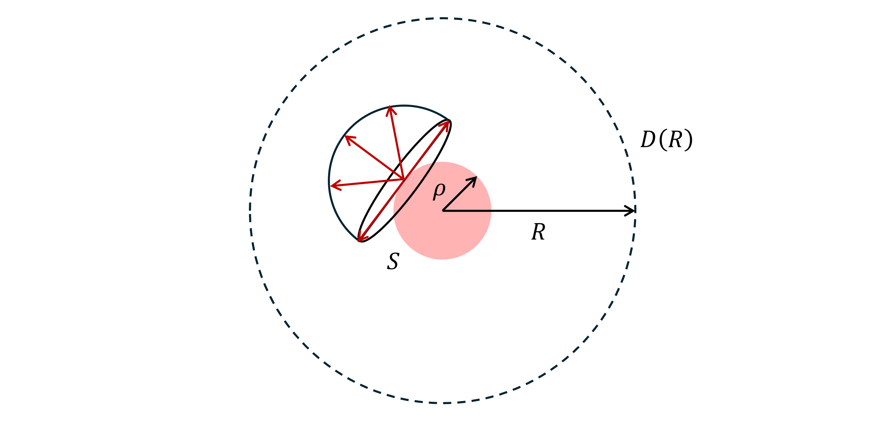
Figure 3 A spherical light-emitting surface. Each point emits light in every direction above the tangent plane.
Suppose light is emitted from a sphere $S$ of radius $\rho$, such as a perfectly round light bulb or the Sun. Each point on the light source emits light in every direction above the tangent plane at that point. Let's calculate the etendue at the concentric spherical surface $D(R)$ of radius $R>\rho$.
Since every point on $D(R)$ receives identical angular range of light, the etendue integral can be split into two parts - the area integral and the solid angle integral:
$$G = \int_{D(R)} \int_\Omega n^2 dS \cos \theta d\Omega = \int_{D(R)} dS \int_\Omega \cos \theta d\Omega$$
The refractive index $n$ is assumed as unity. The area integral leads to the total area of $D(R)$:
$$\int_{D(R)} dS = 4\pi R^2$$
For the solid angle integral, notice that each point on $D(R)$ receives, and thus is traversed by, a cone of light with a half-angle $\theta_0 = \sin^{-1} \left(\frac{\rho}{R}\right)$. This leads to:
$$\int_\Omega \cos \theta d\Omega = \int_0^{2\pi} \int_0^{\theta_0} \cos \theta \sin\theta d\theta d\phi = \pi \sin^2 \theta_0 = \pi \left(\frac{\rho}{R}\right)^2$$
Plugging these results back into our original equation, we obtain:
$$G = 4\pi R^2 \times \pi \left( \frac{\rho}{R} \right)^2 = 4\pi^2 \rho^2$$
It should be emphasized that the etendue value does not depend on $R$. The etendue remains exactly the same no matter which surface we evaluate it on.
Example 3: Etendue of Light Refracted by a Lens
Suppose that the light-emitting surface discussed in Example 1 is placed perpendicular to the optical axis at position $z=z_o$, acting as the object of a lens system. The lens system consists of a single lens located at the origin of the optical axis, shaped as a disk of diameter $D$. The diameter is sufficiently small to apply the paraxial approximation. The lens forms the image of the object at $z=z_i$, such that the well-known imaging condition, $\frac{1}{z_o} + \frac{1}{-z_i} = \frac{1}{f}$, is satisfied. The magnification of this lens system is defined as $M = \frac{z_i}{z_o}$.
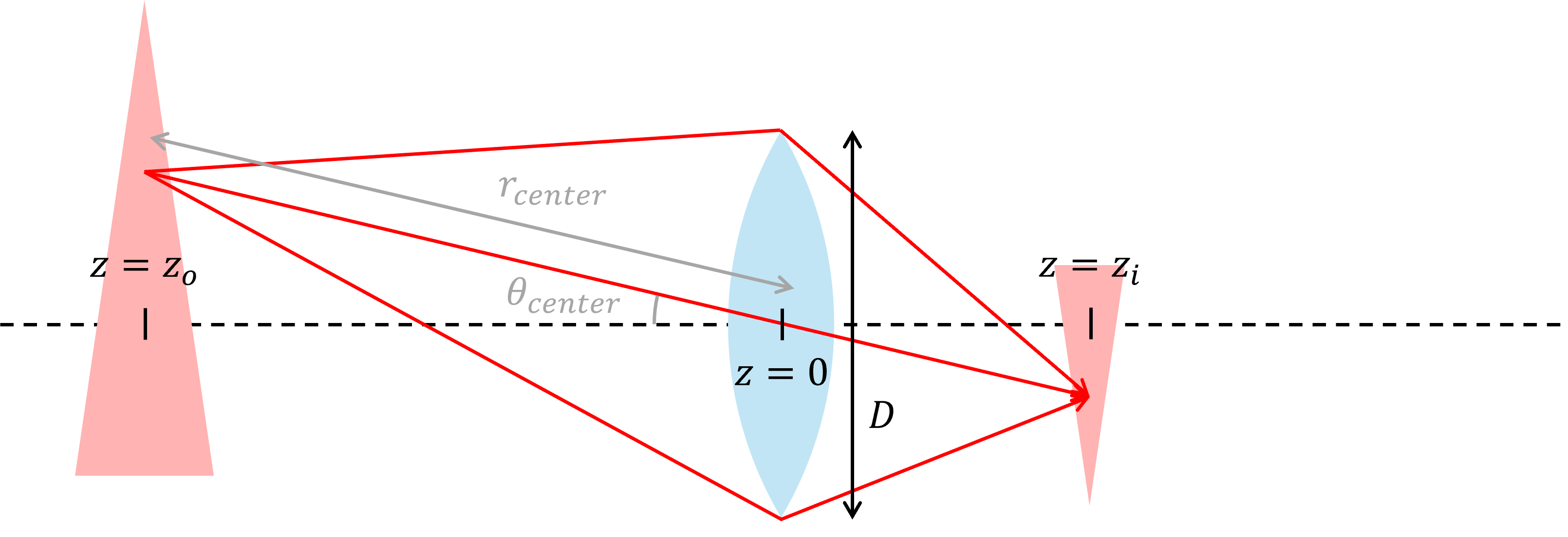
Figure 4 A lens imaging an object.
A point on the object, located at $(x_o, y_o, z_o)$, forms its image at $(x_i, y_i, z_i) = (Mx_o, My_o, Mz_o)$. In order to evaluate the solid angle integral of the etendue at both object and image points, we first consider an arbitrary point $(x,y,z)$. The solid angle integral of the lens surface viewed from this point is:
$$\int_\Omega \cos \theta d\Omega = \int_\Sigma \cos \theta \frac{d\Sigma \cos \theta}{r^2} = \int_\Sigma \frac{\cos^2 \theta}{r^2} d\Sigma $$
where $\Sigma$ denotes the lens surface, and $\theta$ is the angle of the light ray from the object point to the lens' surface element $d\Sigma$. $r$ is the distance between the object point and $d\Sigma$, so that the infinitesimal solid angle of $d\Sigma$ viewed from the object point is derived as $d\Omega = \frac{d\Sigma \cos \theta}{r^2}$.
Now we apply the paraxial approximation: the lens is small enough that the distance and the angle of the light ray connecting the object point to $d\Sigma$ can be approximated as those to the center of the lens:
$$\theta \approx \theta_{center} = \tan^{-1}\left|\frac{\sqrt{x^2+y^2}}{z}\right|, \ r \approx r_{center} = \sqrt{x^2+y^2+z^2}$$
Recall that without this paraxial approximation, the image of the object point is not perfectly concentrated on the image point calculated by the imaging condition due to the fundametal aberrations of a spherical lens.
Utilizing these results, we obtain the following solid angle integral:
$$\int_\Omega \cos \theta d\Omega = \int_\Sigma \frac{\cos^2 \theta}{r^2} d\Sigma = \frac{\cos^2 \theta_{center}}{r_{cneter}^2} \int_\Sigma d\Sigma = \frac{z^2}{(x^2+y^2+z^2)^2} \frac{\pi D^2}{4}$$
This yields the solid angle integrals at the object point and the image point as follows:
$$\int_{\Omega_o}\cos\theta d\Omega_o = \frac{z_o^2}{(x_o^2+y_o^2+z_o^2)^2} \frac{\pi D^2}{4}$$ $$\int_{\Omega_i}\cos\theta d\Omega_i = \frac{z_i^2}{(x_i^2+y_i^2+z_i^2)^2} \frac{\pi D^2}{4} = \frac{1}{M^2}\frac{z_o^2}{(x_o^2+y_o^2+z_o^2)^2} \frac{\pi D^2}{4}$$
Now, we integrate them over the entire object surface $S_o$ and image surface $S_i$, respectively, to obtain the etendue $G_o$ at the object and $G_i$ at the image:
$$G_o = \int_{S_o} \left[\int_{\Omega_o}\cos\theta d\Omega_o \right] dS_o = \frac{\pi D^2}{4}\int_{S_o} \frac{z_o^2}{(x_o^2+y_o^2+z_o^2)^2} dx_o dy_o$$ $$G_i = \int_{S_i} \left[\int_{\Omega_i}\cos\theta d\Omega_i \right] dS_i = \frac{\pi D^2}{4}\int_{S_i} \frac{1}{M^2}\frac{z_o^2}{(x_o^2+y_o^2+z_o^2)^2} dx_i dy_i = \frac{\pi D^2}{4}\int_{S_i} \frac{1}{M^2}\frac{z_o^2}{(x_o^2+y_o^2+z_o^2)^2} (Mdx_o) (Mdy_i) = \frac{\pi D^2}{4}\int_{S_o} \frac{z_o^2}{(x_o^2+y_o^2+z_o^2)^2} dx_o dy_o$$
Again, the refractive index was assumed as $n=1$. Observe that the calculation results of $G_o$ and $G_i$ are identical. We can conclude that the etendue remains constant during imaging by a lens.
Conservation of Etendue
The two examples we inspected, namely Example 2 and Example 3, provide a hint towards a more general property: etendue is conserved. One might think that paraxial approximation was required in Example 3, but this approximation is only needed to ensure that the image of an object point is formed as a single point without aberrations, making the calculations much simpler. In fact, it has nothing to do with the etendue conservation.
The conservation of etendue holds true for geometric optics, where we view light as a collection of rays, neglecting the wave-like nature of light such as diffraction. However, we need some understanding on Hamiltonian optics in order to prove this conservation.
Hamiltonian optics start from Fermat's priciple, which states the the optical path length of a light ray is at a stationary point. In mathematical form, this is expressed using the form of the variational method:
$$\delta S = \delta\int_A^B nds = \delta \int_{x_{3A}}^{x_{3B}} n(x_1, x_2; x_3)\sqrt{1 + \left( \frac{dx_1}{dx_3} \right)^2 + \left( \frac{dx_2}{dx_3} \right)^2} dx_3 = 0$$
This corresponds to the Principle of Least Action in Hamiltonian mechanics with a Lagrangian $\mathcal{L} := n(x_1, x_2; x_3)\sqrt{1 + \left( \frac{dx_1}{dx_3} \right)^2 + \left( \frac{dx_2}{dx_3} \right)^2}$.
We can then define the momenta:
$$p_k := \frac{\partial L}{\partial\dot{x_k}} = n(x_1, x_2; x_3)\frac{\dot{x_k}}{\sqrt{1+\dot{x_1}^2+\dot{x_2}^2}} = n \frac{dx_k}{ds}, \ k=1,2$$
where $\dot{x_k} := \frac{dx_k}{dx_3}$, to obtain the Hamiltonian of the system:
$$\mathcal{H} := \sum_{k=1,2} \dot{x_k}p_k - \mathcal{L}$$
Fermat's principle is equivalent to solving the following Hamilton's equations, as in classical Hamiltonian mechanics:
$$\frac{\partial \mathcal{H}}{\partial x_k} = -\dot{p_k},\ \frac{\partial \mathcal{H}}{\partial p_k} = \dot{x_k}$$
Any light ray at a particular moment of $x_3$ can be expressed as a point $(x_1, x_2, p_1, p_2)$ in phase space. We may formulate the infinitesimal phase space volume $d\Gamma$ of an infinitesimal bundle of light rays as:
$$d\Gamma = dx_1 dx_2 dp_1 dp_2$$
Let's express the direction of this bundle of light rays using the polar angle $\theta$ and the azimuthal angle $\phi$, using the $x_3$-axis as the polar axis. The momenta are then derived as $p_1 = n \sin \theta \cos \phi$ and $p_2 = n \sin \theta \sin \phi$, leading to:
$$dp_1 dp_2 = \left|\frac{\partial(p_1, p_2)}{\partial (\theta,\phi)}\right|d\theta d\phi = n^2 \cos \theta \sin \theta d\theta d\phi$$
Therefore, we obtain the phase space volume element $d\Gamma$ as follows:
$$d\Gamma = n^2 dx_1 dx_2 \cos \theta \sin \theta d\theta d\phi = n^2 dS \cos \theta d \Omega = dG$$
Observe that since $dx_1 dx_2$ and $\sin \theta d\theta d\phi$ are the area $dS$ and the solid angle $d\Omega$ of the light bundle, respectively, $d\Gamma$ becomes identical to the definition of etendue $dG$. Therefore, the total etendue $G$ of arbitrary light rays is exactly the same as their total phase space volume.
Now, let's investigate how the phase space volume changes according to the evolution of $x_3$. Each point on the surface $\partial\Gamma$ enclosing the phase space volume $\Gamma$ moves with a generalized velocity of $\mathbf{v} = (\dot{x_1}, \dot{x_2}, \dot{p_1}, \dot{p_2})$. This increases the volume of the phase space by an amount of $(\mathbf{v} \cdot \mathbf{n}dS) \delta x_3$, where $\mathbf{n}$ and $dS$ denotes the unit normal vector and the surface element of $\partial \Gamma$, respectively. Thus, the total increment of the phase space volume during $\delta x_3$ is:
$$\delta \Gamma =\int_{\partial \Gamma} (\mathbf{v}\cdot \mathbf{n}dS)\delta x_3 = \delta x_3 \int_{\partial \Gamma} (\mathbf{v}\cdot \mathbf{n})dS = \delta x_3 \int_\Gamma \nabla \cdot \mathbf{v} d\Gamma$$
Here, the divergence theorem is applied for the second equality. Meanwhile, the term $\nabla \cdot \mathbf{v}$ is further simplified utilizing the Hamilton's equations:
$$\nabla \cdot \mathbf{v} = \frac{\partial \dot{x_1}}{\partial x_1} + \frac{\partial \dot{x_2}}{\partial x_2} + \frac{\partial \dot{p_1}}{\partial p_1} + \frac{\partial \dot{p_2}}{\partial p_2} = \frac{\partial^2 \mathcal{H}}{\partial x_1\partial p_1}+ \frac{\partial^2 \mathcal{H}}{\partial x_2\partial p_2} - \frac{\partial^2 \mathcal{H}}{\partial p_1\partial x_1} - \frac{\partial^2 \mathcal{H}}{\partial p_2\partial x_2} = 0$$
Therefore, we obtain $\delta \Gamma = 0$. This proves that the phase space volume remains invariant, and so does etendue. However, it is worth emphasizing again that this is only true for geometric optics, where light is expressed as a collection of light rays: we have explicitly used this assumption while establishing the principles of Hamiltonian optics.
Impact of Etendue Conservation in AR/VR Optics: The Fundamental Trade-off
The invariant nature of etendue imposes a critical limitation on the development of AR/VR devices. AR/VR systems inject light emitted from a light engine into the entrance pupil of an optical system, which in turn creates an image at a distance large enough for eye accommodation through the exit pupil of the system. In these applications, there are two important factors to be maximized for the user experience: the field of view (FOV) and the eyebox. The FOV is the angle extent over which the user sees the displayed image. A larger FOV provides the user with a wider view, ideally approaching the maximum limit of human vision. The eyebox is the positional range over which a human eye can move while still observing the full image. A larger eyebox makes the performance of the glasses less sensitive to the user's eye position variation, potentially caused by inter-user variations and accidental misalignments.
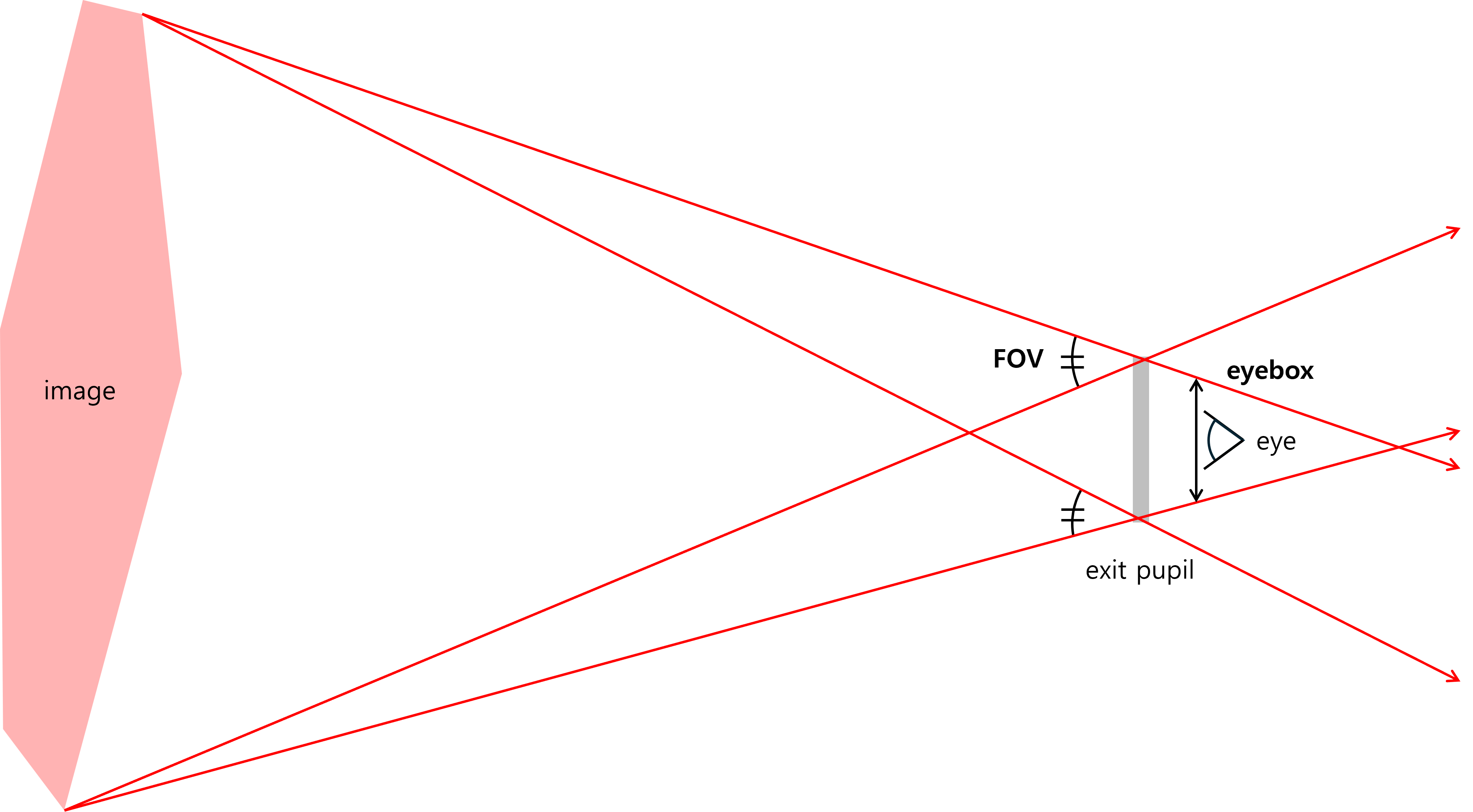
Figure 5 A conceptual image of ray tracing in an AR/VR device.
Figure 5 depicts a conceptual model of an AR/VR device. The image is assumed to be sufficiently far away compared to the dimensions of the device, so that the light rays originating from a particular point in the image pass through the exit pupil parallel to each other.
The etendue value is determined at the moment light from the light engine enters the optical system's entrance pupil. Assuming the system consists of elements well-described by geometric optics, such as mirrors and lenses, this initially determined etendue is strictly conserved until the light exits the system through the exit pupil. Denoting the angular diameter of the image as $2\Theta$ and the area of the exit pupil as $A$, the etendue $G$ is calculated in the same way done in Example 1:
$$G = A \times \pi \sin^2 \Theta$$
The angle $2\Theta$ corresponds to the FOV of this AR/VR device. As the FOV ($2\Theta$) is increased, the area of the exit pupil $A$ must decrease since the total etendue $G$ remains constant. This eventually results in a smaller eyebox. Therefore, a trade-off exists between the FOV and the eyebox. One cannot improve both the FOV and the eyebox no matter how sophisticated the design of the (geometrical) optical system is.
In modern AR/VR devices, this fundamental trade-off is circumvented through the use of non-geometric optical elements, where the wave-like nature of light plays a dominant role. For instance, a diffraction grating can split a single light ray into multiple angular paths, resulting in an enlarged etendue. Various types of diffraction gratings are utilized particularly in waveguide-type combiner optics of modern AR glass products to expand the eyebox while maintaining the FOV, a process commonly referred to as exit pupil expansion (EPE).